A Model Transformation Approach for Automatic Composition of COTS User Interfaces in Web-Based Information Systems
Developed work for Jornal Information System Management (JISM)
Globalization of the information and the Knowledge Society require the modernization of Web-based Information Systems (WIS) into evolutive and adaptable user interfaces. Nowadays, WIS user interfaces are built following traditional development paradigms. This paper is inspired on a Model-Driven Development (MDD) perspective to produce runtime automatic composition of user interfaces from model and metamodel representations of widgets-type COTS interface components architectures and model transformation.
| 1. Example Scenario | |
| 1.1. User Interface | |
| 1.2. Use Case Diagram | |
| 1.3. User Interaction Diagram | |
| 2. Model Transformation | |
| 2.1. Metamodel | |
| 2.2. Model | |
| 2.3. Transformation | |
| 3. Graphic Tool | |
| 3.1. Steps of process | |
Our proposal is just inspired on the widgets components of an iGoogle interface. Due to their Web nature and simplicity, these interfaces (and components) are satisfactorily applicable in WIS environments. However, there are no dependences between components and such dependences are not adecuate to be used in WIS cooperative environments, where different groups of people and at different places simultaneously interact the interface for decisionmaking.
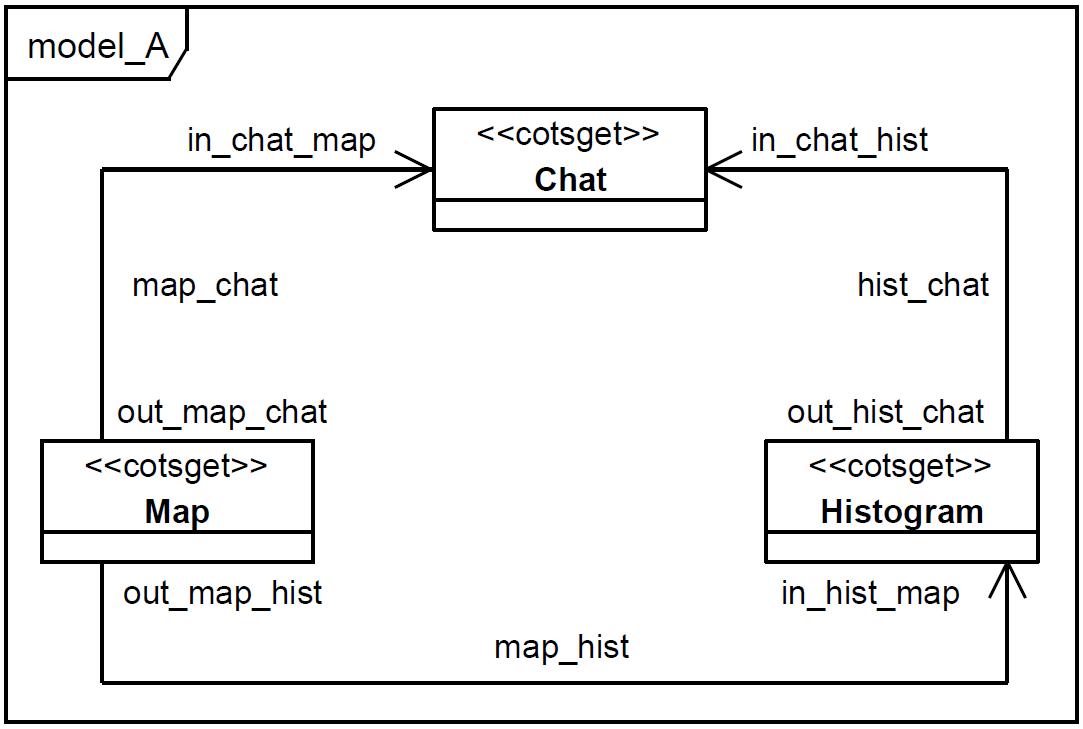
An EMIS such as SOLERES manages environmental information like cartographical maps and satellite images. To describe how we used the model transformation in the methodology, let’s suppose an EMIS user interface as shown in the next figure:
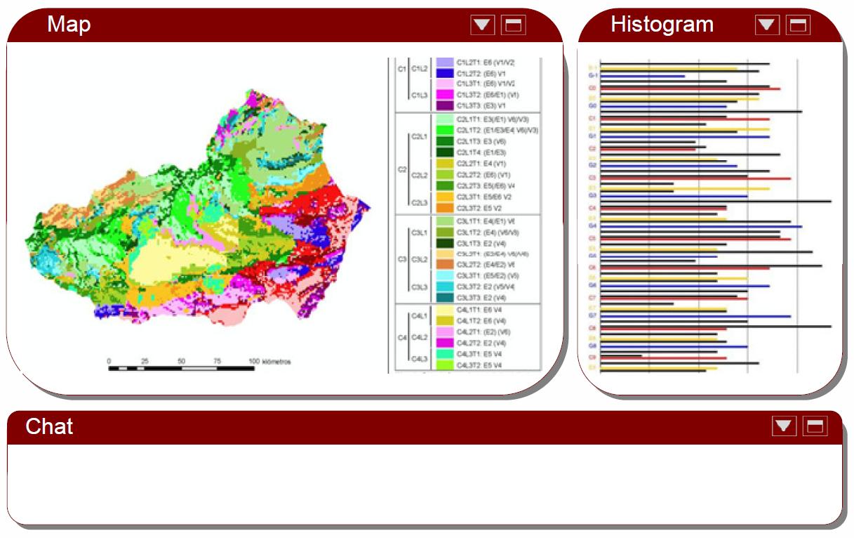
The interface has a similar shape to iGoogle’s. It is composed of three interface components (three cotsgets): a cartographical map, a histogram related to the map and a Chat component.
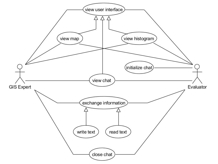
In this scenario, two system users are supposed to be simultaneously accessing the interface for coordination tasks in decision-making. On the one hand, there is a user playing the role of Evaluator, who is carrying out an environmental impact assessment study and then he/she may need some advice from a GIS expert. Next figure shows the use case diagram of the environment described:
Next figure shows a sequence diagram, which explains the users interaction with the interface and the interaction between the classes that depend on it.
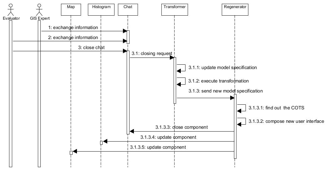
The process starts when both users require coordination through a "Chat". Both visualize a shared interface similar to the figure showed previously. Through "Chat" component, they make query and consensus operations and once they have finished, the Evaluator closes the "Chat" (step #3). After that, a request is internally made to the transformer so that it updates the architecture model that both users are currently visualizing (architecture with three components). This model updating refers to the interaction upon an interface element, which must be reflected in the model. Once the model has been changed to show this interaction, the transformer is executed (#3.1.2), and the result is a new interface model (#3.1.3). From the new model, the second step consists of regenerating the interface from those restrictions imposed in the interface architecture (the model). This process is a trading service that selects the specific components satisfying the needs of such architecture. Due to the simplicity of the example, this process generates the same interface components except "Chat" which was no longer imposed in the architecture (it was not in the model). Given the fact that the article focuses on transformation, not on reconstruction, we preferred to present quite a simple example to explain the model transformation process.
Model transformation is a general framework of software engineering in which some (visual) models are transformed into other models. In UML (Unified Modeling Language), models represent instances of UML diagrams (class diagrams, state machines, sequence diagrams, etc.); such instances can be transformed in order to have different views of the same model, or to obtain code in a particular programming language, among other examples. Describing model transformations not only requires specific languages for their definitions but also a meta-model to abstract any model instance.
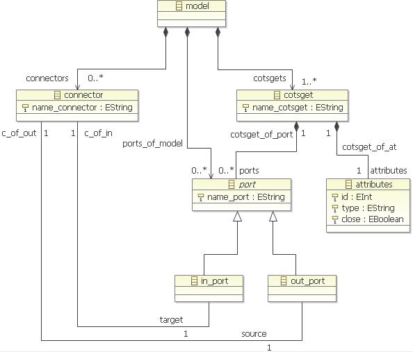
Given an MDD approach, we defined a UML profile to represent user interface architectures made up of cotsgets components. The profile was described through a UML meta-model shown in next figure:
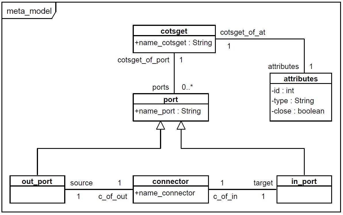
The meta-model establishes the rules and elements that describe interface architecture through a model (an instance of the meta-model). Here, interface architecture of cotsgets components defines different aspects not only of the interface itself (i.e. visual aspects, position, etc.) but also dependences between components, simple interaction (individual) or complex (cooperative), among other aspects. The present work is based only on dependences between components. Thus, we’ll consider interface architecture as a set of components with dependences between them.
An interface component is a component that offers a service and may
require others’ service to work. For example, next figure shows a user
interface architecture for the scenario described in Section 1 and it
visually corresponds to the showed user interface. Dependences between
the three components are unknown in the graphical user interface;
however, in its associated
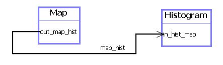
model (next figure) the "Map" component is offering a service to the
"Histogram" component, that is, the interface portion drawing the
histogram is associated to an input diagram. In addition, "Chat" is
requiring some information from "Map" and "Histogram". Components are
defined by means of an empty and stereotyped UML class like "<
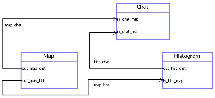
Dependences are represented by UML associations (called "connector"): with a name and two roles. Roles beginning by "out" label represent a service offer (component’s behaviour). The role name is created by adding the name of the component associated to the role and the name of the component that is connecting. For instance, a "map_chat" connector can link two cotsgets components called "map" and "chat". The order in the name indicates the dependence’s direction. The source is called as "out_map_chat" offer role, and the target "in_chat_map". In the latter, the role "in" means that the component is requiring a service as an input. Thus, roles "in" are represented as an arrow in the connector.
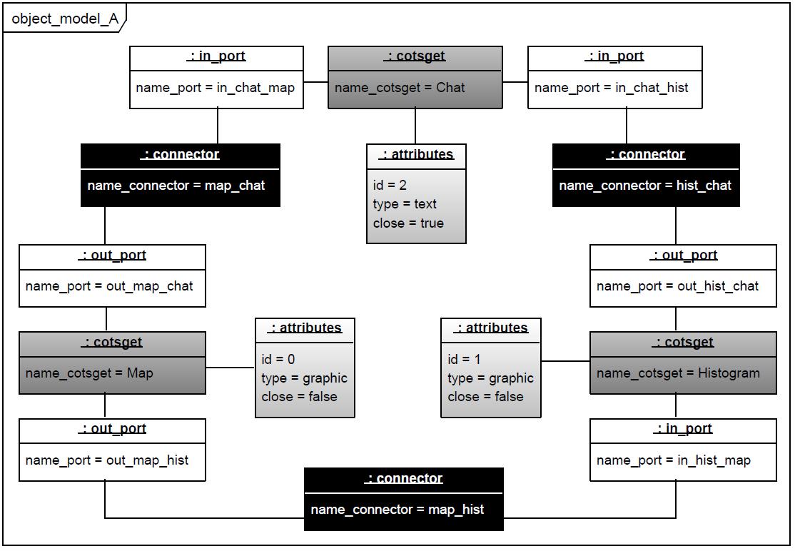
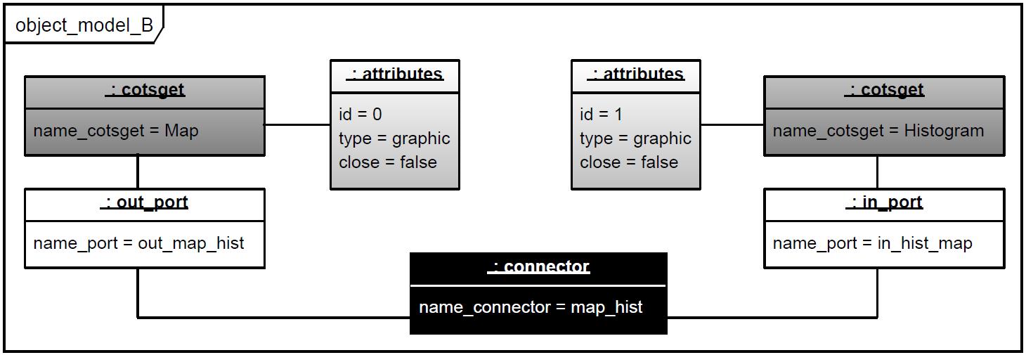
The model transformation process makes a change in the interface of the associated architecture (model B), starting from an initial situation of user interface established through cotsgets (model A) and a user interaction with an element of a user interface component. As previously advanced, the example scenario starts from a model with three cotsgets components. When one of the users interacts with a close element in the Chat component, the transformer changes the initial model into an architecture with two cotsgets components. Therefore, the transformation process works on the meta-model and the object models, which are instances of the meta-model user interfaces. Next figures show UML object diagrams of object models in the source and target architecture (models A and B). Such diagrams are stored in XMI notation (used by the model transformation process).
Next, we show the ATL code that transforms the source interface provided by the model A into another B, once the "Close" button has been clicked. The input metamodel ("intMM") and the output metamodel ("outMM") are the same, defined as "meta_model.core" (lines #1 to #5). The transformation program defines a rule for each meta-model element, that is, a rule for "cotsget” elements (#7 to #11), another for "attributes" (#13 to #17), another for "in_port"(#19 to #25), "out_port" (#27 to #34) and "connector" (#36 to #44). The last rule (#46 to #50) copies the root element (model) to the new target model by adding its properties (cotsgets and connectors).
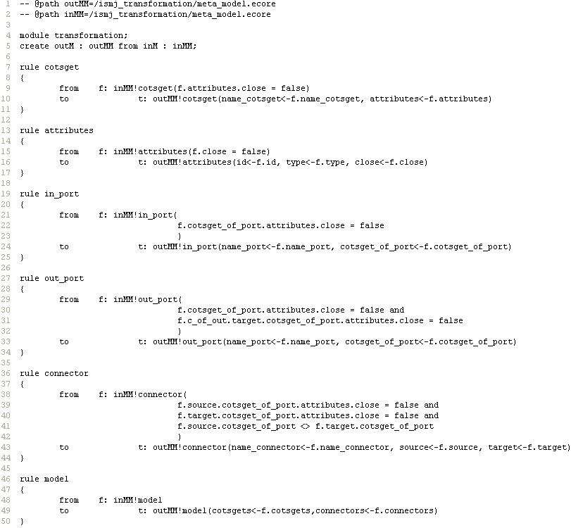
The transformer copies those input model elements that depend on a cotsget component having a "close" attribute with value "false". Such elements remain on the target. Those that depend on a component with its "close" attribute set to "true", are not copied to the model B. The "cotsget" rule (#7 to #11) changes each element of cotsget type ("inMM/cotsget") of the in metamodel ("inMM") that has a false close attribute ("attribute.close=false") in the same element of the target model, by copying the value of its properties "name_cotsget" and "attributes" (i.e., "name_cotsget<-f.name_cotsget, attributes<-f.attributes"). The "Connector" rule (#36 to #44) changes each connector element of the in metamodel ("inMM"), whose input and output ports belong to a father with its "Close" attribute set to "false" and both belong to different component, into the same element by copying the value of all its attributes (name, source component and target component). The reflexive restriction previously mentioned is checked for a connector. The transformation occurs if and only if the source component and the target component are different.
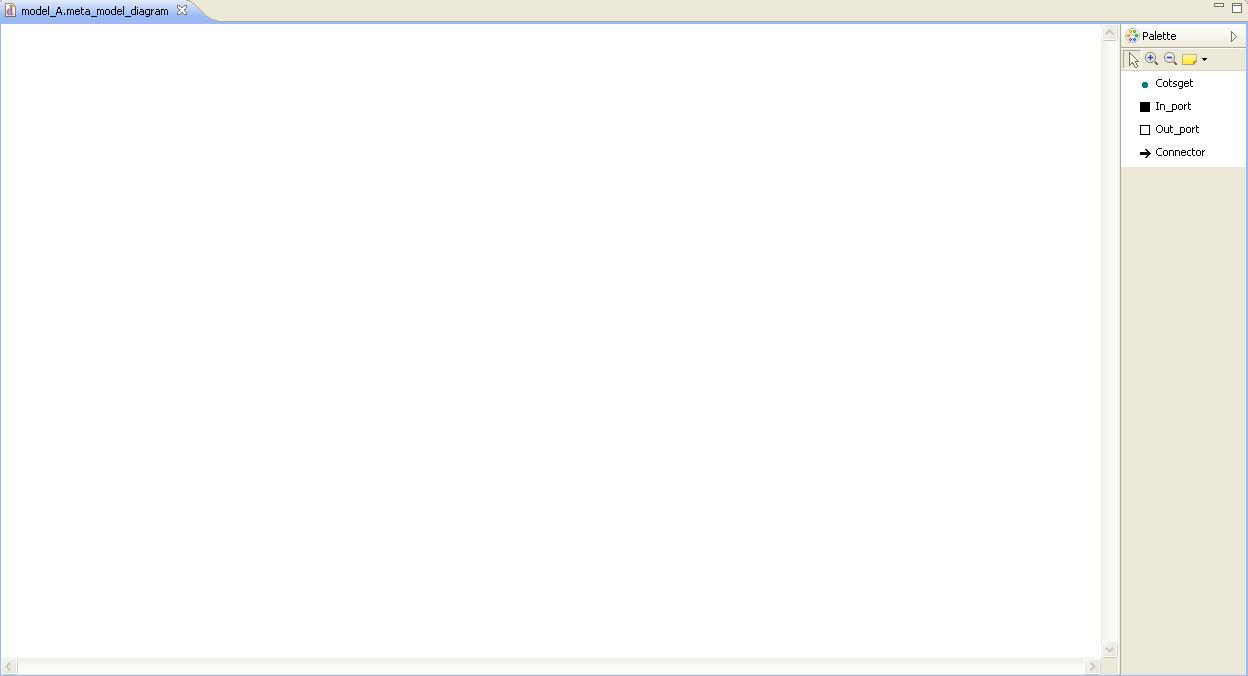
An Eclipse GMF tool allows to draw (map) models of cotsgets architectures (as shown in Section 2. The name attribute of the connector is mapped as association name and the name attributes of "out_port" and "in_port" classes are mapped as role names in the model. Moreover, the arrow of the association line (dependence) is placed at the end of "in_port" class of the object model. Dependences are mapped as "connector" elements in the object diagram. We will see how those attributes considered as private ("-") in the metamodel appear in the object model (the diagram) and not in the architecture model.
1. The first step is to define a meta-model in EMF. This meta-model describes our system prototipe architecture. From this meta-model, we can define user interface models built based on components (cotsget). On this models, we also represent dependencies behind system components.
2. Eclipse Modeling framework let us to develop a graphic tool from the meta-model; Graphical Modeling Framework (GMF) specifically. We use this tool to build component models of the architecture.
3. For example, we define a start model with three components (Map, Histogram and Chat) and their dependencies.
4. The next step is to modify the built model. For this, we must rename the model from the .meta_model to the .xmi extension. Then, we can change the value of the model attributes through the "Sample Reflective Ecore Editor" from Eclipse Modeling Framework. In our case, these changes will simulate user events. For this example, we simulate the closing chat component event and we change to "true" the "close" atribute value of chat component.
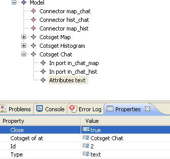
5. Define a M2M (Model-to-Model) transformation. Both, the input model and the output model have the same reference meta-model. This transformation is developed in ATL and its rules are intended to copy the input model components to the output model, except those components that have a "close" attribute value to "true", those ports contained in closing components or conected with components will be closed, and the connectors that link component ports are going to be closed. Defined rules are the same we showed in Section 2 - Transformation:
6. Executing the transformation, we get the next output model with XMI extension. We can see as a component has been deleted such as their related ports and connectors of the model:
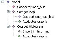
7. We rename the transformation output model from .xmi to .meta_model (or the plugin extension name we have decided). Then, we do right-click and select "Initializate meta_model_diagram diagram file…" and we get the diagram of the new model.