A connection-oriented packet switching technology. Industry standard, switched, Data Link layer protocol that handles multiple virtual circuits. Frame Relay is a next generation protocol after X.25. Frame Relay eliminates some of the time-consuming processes (such as error correction and flow control) employed in X.25.
The packet identifier (see switching ...) is called Data Link Connection Identifier (DLCI).
Frame Relay is a high-performance WAN protocol that operates at the physical and Data Link layers of the OSI reference model.
The Frame Relay design provides packet-switched data transfer with minimum end-to-end delays. The original design omits anything that might contribute to delay (for example, dynammic routing that could mess packets).
Eric Scace, an engineer at Sprint International, invented Frame Relay as a simpler version of the X.25 protocol to use across Integrated Services Digital Network (ISDN) interfaces. Today, it is used over a variety of other network interfaces as well. When Sprint first implemented Frame Relay in its public network, they used StrataCom switches. Cisco’s acquisition of StrataCom in 1996 marked their entry into the carrier market.
Frame Relay has become the most widely used WAN technology in the world. Large enterprises, governments, ISPs, and small businesses use Frame Relay, primarily because of its price and flexibility. As organizations grow and depend more and more on reliable data transport, traditional leased-line solutions are prohibitively expensive.
Using leased lines, each site is connected through a switch at the local telephone company’s central office (CO) through the local loop, and then across the entire network. Customers are paying for the end-to-end circuit regardless of how much bandwidth it uses. A dedicated line provides little practical opportunity for a one-to-many connection without getting more lines from the network provider. The leased-line design also limits flexibility. Unless circuits are already installed, connecting new sites typically requires new circuit installations and takes considerable time to implement.
Frame Relay network uses permanent virtual circuits (PVCs). A PVC is the logical path along an originating Frame Relay link, through the network, and along a terminating Frame Relay link to its ultimate destination. In a network with Frame Relay access, a PVC uniquely defines the path between two endpoints.
Frame Relay is a more cost-effective option for two reasons. First, with dedicated lines, customers pay for an end-to-end connection. That includes the local loop and the network link. With Frame Relay, customers only pay for the local loop, and for the bandwidth they purchase from the network provider. Distance between nodes is not important. While in a dedicated-line model, customers use dedicated lines provided in increments of 64 kb/s, Frame Relay customers can define their virtual circuit needs in far greater granularity, often in increments as small as 4 kb/s.
The second reason for Frame Relay’s cost effectiveness is that it shares bandwidth across a larger base of customers. Typically, a network provider can service 40 or more 56 kb/s customers over one T1 circuit. Using dedicated lines would require more DSU/CSUs (one for each line) and more complicated routing and switching. Network providers save because there is less equipment to purchase and maintain.
Frame Relay has lower overhead than X.25 because it has fewer capabilities. For example, Frame Relay does not provide error correction, modern WAN facilities offer more reliable connection services and a higher degree of reliability than older facilities. The Frame Relay node simply drops packets without notification when it detects errors. Any necessary error correction, such as retransmission of data, is left to the endpoints. This makes propagation from customer end to customer end through the network very fast.
As a data link protocol, Frame Relay provides access to a network, delimits and delivers frames in proper order, and recognizes transmission errors through a standard Cyclic Redundancy Check. As a network protocol, Frame Relay provides multiple logical connections over a single physical circuit and allows the network to route data over those connections to its intended destinations.
In Frame Relay, the end of each connection has a number to identify it called a Data Link Connection Identifier (DLCI). Any station can connect with any other simply by stating the address of that station and DLCI number of the line it needs to use.
Service providers build Frame Relay networks using very large and very powerful switches, but as a customer, your devices only see the switch interface of the service provider. Customers are usually not exposed to the inner workings of the network, which may be built on very high-speed technologies, such as T1, T3, SONET, or ATM.
From a customer’s point of view then, Frame Relay is an interface and one or more PVCs. Customers simply buy Frame Relay services from a service provider.
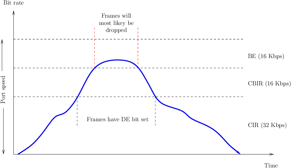
Customers simply buy Frame Relay services from a service provider. However, before considering how to pay for Frame Relay services, there are some key terms and concepts to learn, as illustrated in the figure:
From a customer’s point of view, the service provider provides a serial connection or access link to the Frame Relay network over a leased line. The speed of the line is the access speed or port speed. Access rate is the rate at which your access circuits join the Frame Relay network. These are typically at 56 kb/s, T1 (1.536 Mb/s), or Fractional T1 (a multiple of 56 kb/s or 64 kb/s). Port speeds are clocked on the Frame Relay switch. It is not possible to send data at higher than port speed.
Customers negotiate CIRs with service providers for each PVC. The CIR is the amount of data that the network receives from the access circuit. The service provider guarantees that the customer can send data at the CIR. All frames received at or below the CIR are accepted.
A great advantage of Frame Relay is that any network capacity that is being unused is made available or shared with all customers, usually at no extra charge. This allows customers to "burst" over their CIR as a bonus.
Because the physical circuits of the Frame Relay network are shared between subscribers, there will often be time where there is excess bandwidth available. Frame Relay can allow customers to dynamically access this extra bandwidth and "burst" over their CIR for free.
Bursting allows devices that temporarily need additional bandwidth to borrow it at no extra cost from other devices not using it. A device can burst up to the access rate and still expect the data to get through. The duration of a burst transmission should be short, less than three or four seconds. If long bursts persist, then a higher CIR should be purchased.
Various terms are used to describe burst rates including the Committed Burst Information Rate (CBIR) and Excess Burst (BE) size (also named Excess Information Rate (EIR)).
The CBIR is a negotiated rate above the CIR which the customer can use to transmit for short burst. It allows traffic to burst to higher speeds, as available network bandwidth permits. However, it cannot exceed the port speed of the link. A device can burst up to the CBIR and still expect the data to get through. The duration of a burst transmission should be short, less than three or four seconds.
Frames submitted at this level are marked as Discard Eligible (DE) in the frame header, indicating that they may be dropped if there is congestion or there is not enough capacity in the network. Frames within the negotiated CIR are not eligible for discard (DE = 0). Frames above the CIR have the DE bit set to 1, marking it as eligible to be discarded, should the network be congested.
The BE is the term used to describe the bandwidth available above the CBIR up to the access rate of the link. Unlike the CBIR, it is not negotiated. Frames may be transmitted at this level but will most likely be dropped.
Service providers sometimes sell more capacity than they have on the assumption that not everyone will demand their entitled capacity all of the time. This oversubscription is analogous to airlines selling more seats than they have in the expectation that some of the booked customers will not show up. Because of oversubscription, there will be instances when the sum of CIRs from multiple PVCs to a given location is higher than the port or access channel rate. This can cause traffic issues, such as congestion and dropped traffic.
The connection through a Frame Relay network between two DTEs is called a virtual circuit (VC). The circuits are virtual because there is no direct electrical connection from end to end. The connection is logical, and data moves from end to end, without a direct electrical circuit. With VCs, Frame Relay shares the bandwidth among multiple users and any single site can communicate with any other single site without using multiple dedicated physical lines.
There are two ways to establish VCs:
SVCs, switched virtual circuits, are established dynamically by sending signaling messages to the network (CALL SETUP, DATA TRANSFER, IDLE, CALL TERMINATION).
PVCs, permanent virtual circuits, are preconfigured by the carrier, and after they are set up, only operate in DATA TRANSFER and IDLE modes. Note that some publications refer to PVCs as private VCs.
VCs provide a bidirectional communication path from one device to another. VCs are identified by DLCIs. DLCI values typically are assigned by the Frame Relay service provider (for example, the telephone company). Frame Relay DLCIs have local significance, which means that the values themselves are not unique in the Frame Relay WAN. A DLCI identifies a VC to the equipment at an endpoint. A DLCI has no significance beyond the single link. Two devices connected by a VC may use a different DLCI value to refer to the same connection.
The DLCI is stored in the address field of every frame transmitted to tell the network how the frame should be routed. The Frame Relay service provider assigns DLCI numbers. Usually, DLCIs 0 to 15 and 1008 to 1023 are reserved for special purposes. Therefore, service providers typically assign DLCIs in the range of 16 to 1007.
| Leg | VC | Port | VC | Port |
| A | 102 | 0 | 432 | 1 |
| B | 432 | 4 | 119 | 1 |
| C | 119 | 4 | 579 | 3 |
| D | 579 | 3 | 210 | 0 |
Frame Relay is statistically multiplexed, meaning that it transmits only one frame at a time, but that many logical connections can co-exist on a single physical line. The Frame Relay Access Device (FRAD) or router connected to the Frame Relay network may have multiple VCs connecting it to various endpoints. Multiple VCs on a single physical line are distinguished because each VC has its own DLCI. This capability often reduces the equipment and network complexity required to connect multiple devices, making it a very cost-effective replacement for a mesh of access lines. With this configuration, each endpoint needs only a single access line and interface. More savings arise as the capacity of the access line is based on the average bandwidth requirement of the VCs, rather than on the maximum bandwidth requirement.
Frame Relay takes data packets from a Network layer protocol, such as IP or IPX1 , encapsulates them as the data portion of a Frame Relay frame, and then passes the frame to the Physical layer for delivery on the wire.
The Physical layer is typically EIA/TIA-232, 449 or 530, V.35, or X.21.
The Frame Relay frame is a subset of the HDLC frame type. Therefore, it is delimited with flag fields. The 1-byte flag uses the bit pattern 01111110. The FCS determines whether any errors in the Layer 2 address field occurred during transmission. The FCS is calculated prior to transmission by the sending node, and the result is inserted in the FCS field. At the distant end, a second FCS value is calculated and compared to the FCS in the frame. If the results are the same, the frame is processed. If there is a difference, the frame is discarded. Frame Relay does not notify the source when a frame is discarded. Error control is left to the upper layers of the OSI model.
The header and trailer are defined by the Link Access Procedure for Frame Relay (LAPF) Bearer Services specification, ITU Q.922-A.
Network (for example, IP addresses) address to DLCI tables can be populated by means of Dynamic Mapping of Static Mapping:
Dynamic address mapping relies on Inverse ARP to resolve a next hop network protocol address to a local DLCI value. The Frame Relay router sends out Inverse ARP requests on its PVC to discover the protocol address of the remote device connected to the Frame Relay network. The router uses the responses to populate an address-to-DLCI mapping table on the Frame Relay router or access server. The router builds and maintains this mapping table, which contains all resolved Inverse ARP requests, including both dynamic and static mapping entries.
Dynamic Inverse ARP relies on the presence of a direct point-to-point connection between two ends.
If the router needs to map the VCs to Network layer addresses, it sends an Inverse ARP message on each VC. The Inverse ARP message includes the Network layer address of the router, so the remote DTE, or router, can also perform the mapping. The Inverse ARP reply allows the router to make the necessary mapping entries in its address-to-DLCI map table. If several Network layer protocols are supported on the link, Inverse ARP messages are sent for each one.
The user can choose to override dynamic Inverse ARP mapping by supplying a manual static mapping for the next hop protocol address to a local DLCI. A static map works similarly to dynamic Inverse ARP by associating a specified next hop protocol address to a local Frame Relay DLCI.
In other situations, a static mapping is the only option. For example, on a hub-and-spoke Frame Relay network, where there are several layer 3 networks (it is a layer-3 star topology), we can use static address mapping on the spoke routers to provide spoke-to-spoke (tips of the star) reachability. Because the spoke routers do not have direct connectivity with each other, dynamic Inverse ARP would not work between them.2 In this case, dynamic Inverse ARP only works between hub and spoke, and the spokes require static mapping to provide reachability to each other.
the LMI is a keepalive mechanism that provides status information about Frame Relay connections between the router (DTE) and the Frame Relay switch (DCE). Every 10 seconds or so, the end device polls the network, either requesting a dumb sequenced response or channel status information. If the network does not respond with the requested information, the user device may consider the connection to be down. When the network responds with a FULL STATUS response, it includes status information about DLCIs that are allocated to that line. The end device can use this information to determine whether the logical connections are able to pass data.
Provide information about PVC integrity by communicating and synchronizing between devices, periodically reporting the existence of new PVCs and the deletion of already existing PVCs. VC status messages prevent data from being sent into black holes (PVCs that no longer exist).
LMI status messages combined with Inverse ARP messages allow a router to associate Network layer and Data Link layer addresses.
Periodically, the router repeats the status inquiry, but subsequent responses include only status changes. After a set number of these abbreviated responses, the network sends a full status message.
Allows a sender to transmit a single frame that is delivered to multiple recipients. Multicasting supports the efficient delivery of routing protocol messages and address resolution procedures that are typically sent to many destinations simultaneously.
Frame Relay, ATM, and X.25 are nonbroadcast multiaccess (NBMA) networks. NBMA networks allow only data transfer from one computer to another over a VC or across a switching device. NBMA networks do not support multicast or broadcast traffic, so a single packet cannot reach all destinations. This requires you to broadcast to replicate the packets manually to all destinations.
Gives connection identifiers global rather than local significance, allowing them to be used to identify a specific interface to the Frame Relay network. Global addressing makes the Frame Relay network resemble a LAN in terms of addressing, and ARPs perform exactly as they do over a LAN.
Provides for an XON/XOFF flow control mechanism that applies to the entire Frame Relay interface. It is intended for those devices whose higher layers cannot use the congestion notification bits and need some level of flow control.
Frame Relay can partition a physical interface into multiple virtual interfaces called subinterfaces. A subinterface is simply a logical interface that is directly associated with a physical interface. Therefore, a Frame Relay subinterface can be configured for each of the PVCs coming into a physical serial interface.
To enable the forwarding of broadcast routing updates in a Frame Relay network, you can configure the router with logically assigned subinterfaces. A partially meshed network can be divided into a number of smaller, fully meshed, point-to-point networks. Each point-to-point subnetwork can be assigned a unique network address, which allows packets received on a physical interface to be sent out the same physical interface because the packets are forwarded on VCs in different subinterfaces.
Recall that using Frame Relay subinterfaces ensures that a single physical interface is treated as multiple virtual interfaces to overcome split horizon rules. Packets received on one virtual interface can be forwarded to another virtual interface, even if they are configured on the same physical interface.
Subinterfaces address the limitations of Frame Relay networks by providing a way to subdivide a partially meshed Frame Relay network into a number of smaller, fully meshed (or point-to-point) subnetworks. Each subnetwork is assigned its own network number and appears to the protocols as if it were reachable through a separate interface. Point-to-point subinterfaces can be unnumbered for use with IP, reducing the addressing burden that might otherwise result.
Frame Relay subinterfaces can be configured in either point-to-point or multipoint mode:
A single point-to-point subinterface establishes one PVC connection to another physical interface or subinterface on a remote router. In this case, each pair of the point-to-point routers is on its own subnet, and each point-to-point subinterface has a single DLCI. In a point-to-point environment, each subinterface is acting like a point-to-point interface. Typically, there is a separate subnet for each point-to-point VC. Therefore, routing update traffic is not subject to the split horizon rule.
In split horizon routing environments, routing updates received on one subinterface can be sent out another subinterface. In a subinterface configuration, each VC can be configured as a point-to-point connection. This allows each subinterface to act similarly to a leased line. Using a Frame Relay point-to-point subinterface, each pair of the point-to-point routers is on its own subnet.
A single multipoint subinterface establishes multiple PVC connections to multiple physical interfaces or subinterfaces on remote routers. All the participating interfaces are in the same subnet. The subinterface acts like an NBMA Frame Relay interface, so routing update traffic is subject to the split horizon rule. Typically, all multipoint VCs belong to the same subnet.
You can use multipoint configurations to conserve addresses. This can be especially helpful if Variable Length Subnet Masking is not being used. However, multipoint configurations may not work properly given the broadcast traffic and split horizon considerations. The point-to-point subinterface option was created to avoid these issues.
Frames arriving at a switch are queued or buffered prior to forwarding. As in any queuing system, it is possible that there will be an excessive buildup of frames at a switch. This causes delays. Delays lead to unnecessary retransmissions that occur when higher level protocols receive no acknowledgment within a set time. In severe cases, this can cause a serious drop in network throughput. To avoid this problem, Frame Relay incorporates a flow control feature.
Frame Relay reduces network overhead by implementing simple congestion-notification mechanisms rather than explicit, per-VC flow control. These congestion-notification mechanisms are the Forward Explicit Congestion Notification (FECN) and the Backward Explicit Congestion Notification (BECN).
They let the router know that there is congestion and that the router should stop transmission until the condition is reversed. BECN is a direct notification. FECN is an indirect one.
The frame header also contains a Discard Eligibility (DE) bit, which identifies less important traffic that can be dropped during periods of congestion. DTE devices can set the value of the DE bit to 1 to indicate that the frame has lower importance than other frames. When the network becomes congested, DCE devices discard the frames with the DE bit set to 1 before discarding those that do not. This reduces the likelihood of critical data being dropped during periods of congestion.
In periods of congestion, the provider’s Frame Relay switch applies the following logic rules to each incoming frame based on whether the CIR is exceeded:
If the incoming frame does not exceed the CIR, the frame is passed. If an incoming frame exceeds the CIR, it is marked DE. If an incoming frame exceeds the CIR plus the BE, it is discarded.
To reduce the flow of frames to the queue, the switch notifies DTEs of the problem using the Explicit Congestion Notification bits in the frame address field.
The FECN bit is set on every frame that the upstream switch receives on the congested link (en otras palabras, en cada uno de los frames que el switch congestionado envía hacia el destino). The BECN bit is set on every frame that the switch places onto the congested link to the downstream switch (en todos los frames que el switch congestionado envía hacia el origen de los frames, con o sin piggybacking).
DTEs receiving frames with the ECN bits set are expected to try to reduce the flow of frames until the congestion clears.
If the congestion occurs on an internal trunk, DTEs may receive notification even though they are not the cause of the congestion.