Ethernet
Vicente González Ruiz
December 25, 2013
Contents
1 Basics
- La red Ethernet fue inventada por Metcalfe y Boggs a mediados de los 70
[2] y apareci comercialmente en 1980.
- Han existido y existen diferentes tecnolog’ias, todas estandarizadas por el
grupo de trabajo IEEE 802.3.
- Fue la primera en su g’enero y actualmente es la tecnolog’ia predominante
en redes de ’area local cableadas.
2 Servicio
- El servicio de Ethernet posee las siguientes caracter’isticas:
- Sin conexi’on: los paquetes de datos (com’unmente llamados
frames) Ethernet se transmiten sin previo aviso.
- No fiable: si un frame llega con errores, Ethernet ’unicamente los
desecha. Y si no llega, no hay ning’un tipo de recuperaci’on de errores.
- Es responsabilidad de las capas superiores transformar este servicio en fiable y
orientado a conexi’on (cuando sea preciso).
3 Topologies
- Ethernet is a start topology where the switches are the key piece to grow as
much as we need. However, designs can incorporate:
- Redundant parallel links: useful for bandwidth aggregation and
link faul resilience. This is useful also when connecting with servers
with several network adapters.
- Redundant non-parallel links: useful to protect the network
against shitches fails.
- Loops: alternative pathds add redudancy againsts general (switches
and links) failures.
4 Nomenclature
- Collision domain: Network area where frames collide.
- Broadcast domain: A collection of interconected switches (without a
router or a Virtual LAN (VLAN) inside.
- Microsegment: Connection that a switch creates when communicates
two network adapters.
5 Port-based VS Shared Memory switches
- Port-based memory switches: Frames are stored in queues (of
previously received frames) that are linked to a specific outgoing port.
- Shared memory switches: All incoming frames are stored in a shared
memory. The switch keeps a map of frame to port link showing where a
packet need to be transmitted.
- The number of frames that can be queued in the switch is normally higher
in shared memory switches.
6 Layer 3 switches
- A Layer 3 switch is a router specially designed to be very proficient in
the task of packet forwarding (wire-speed routing), but can not run any
routing protocol nor use WAN interfaces.
7 Attacks
8 Virtual LANs (VLANs)
VLAN technology allows the separation of large broadcast domains into smaller ones
(VLANs). Smaller broadcasts domains limit the number of devices participating in
broadcasts and allow devices to be separated into functional groupings. It is possible
also to extend a VLAN over several switches, which can be very useful for
networks that are geographically distant and can not be conected using a one
swhich.
Different VLANs are like different networks.
Switch ports belongs to one o more VLANs.
VLANs are identified by numbers and there is two ranges::
- Normal Range VLANs: Identified by a VLAN ID between 1 and 1005,
where IDs 1002 through 1005 are reserved for Token Ring and FDDI
VLANs. Can be managed with by the VLAN Trunking Protocol (VTP)
- Extended Range VLANs: Identified by a VLAN ID between 1006 and
4094. Normally are used by ISPs to extend their infraestructure to a
greater number of customers. Can’t be managed by the VTP.
9 VLAN trunks
The links that connects switches and that transmitt data of different VLANs are
called VLAN trunks. Without VLAN trunks, the number of connections between two
switched should be equal to the number of VLANs that is defined in both switches.
With VLAN trunks, only a link is necessary.
Frames that are transmitten in a VLAN trunk need to be encapsulated in a
802.1Q frame, which adds a header with the tag of the VLAN to that the frame
belongs. There is no difference between a the VLAN’s traffic and a LAN’s
traffic.
10 Types of VLANs
Frames are tagged with a VLAN number that can be used to classify the
frames.
- Default VLAN: When the switch boots, there is only a VLAN defined,
the default VLAN (usually, the VLAN number 1) and all ports belongs to
that VLAN. It is always available and it can not be renamed nor deleted.
The default VLAN is used for protocols such as the Spanning Tree Protocol
(STP).
- Data VLAN (or user VLAN): A VLAN that is configured to carry
only user-generated traffic (email, HTTP, VoIP without QoS, etc.).
- Voice VLAN: Spefifically defined for carry voice data (VoIP) within a
QoS (Quality of Service) context. A switch prioritices voice frames.
- Native VLAN: Used to send non-tagged (native) frames (those that go
over non-trunk ports). If the frame is tagged, the native VLAN drops it.
By default, the native VLAN is the VLAN number 1 (the default VLAN).
See the IEEE 802.1Q specification for more information.
- Nanagement VLAN: Used for management purposes (has an IP address
asigned).
11 VLAN Switch Port Modes
A port can be configure to support these VLAN types:
- Static VLAN: Those ports that are manually assigned to a VLAN.
- Dynamic VLAN: Those ports that are controlled by a VLAN
Membership Policy Server (VMPS).
- Voice VLAN: Those ports that are assigned to a VoIP VLAN,
supporting, for example, a IP telephone.
12 Inter-LAN communication using a layer 3 switch
VLANs act like different (separated LANs). If fact, hosts attached to a VLAN or
other, dones not notice anything special. For this reason, if a host of one VLAN want
to communicate with other hosts of other VLAN we need a router or a layer 3 switch
(that are not the same!):
- Inter-LAN communication using a router: A host-X in VLAN-X sends a
frame to host-Y in VLAN-Y:
- A host-X in the VLAN-X broadcasts an ARP request frame, asking
for the MAC address of the gateway MIC (NIC-X address).
- The request arrives to the gateway and also to the rest of NICs of
the same VLAN-X.
- Only the gateway unicasts an ARP reply frame from its NIC-X
(remember that the router connects the two VLANs and therefore,
there are two links between the router and the switch with defines
the VLANs) to host-X.
- The host-X receives the ARP reply frame.
- The host-X unicasts the data frame to the gateway.
- The gateway receives the data frame through its NIC-X.
- The gateway broadcasts an ARP request frame, in VLAN-Y, from its
NIC-Y asking for the MAC address of NIC of the destination host-Y.
- The ARP request arrives to all the NICs connected to VLAN-Y.
- Only the host-Y unicasts an ARP reply frame towards the gateway’s
NIC-Y.
- The gateway’s NIC-Y receives the ARP reply frame.
- The gateway unicasts the data frame to host-Y.
- Inter-lAN communication using a layer 3 switch: A host-X in VLAN-X
sends a frame to host-Y in VLAN-Y:
- A host-X in the VLAN-X broadcast an ARP request frame, asking
for the MAC address of the gateway’s NIC (NIC-X address).
- The request arrives to the layer 3 switch and also to the rest of NICs
of the same VLAN-X (it is not very useful, but the switch floods the
frame to the rest of ports that belong to the VLAN-X).
- Only the layer 3 switch unicasts an ARP reply frame from its NIC-X
to host-X.
- The host-X receives the ARP reply frame.
- The host-X unicasts the data frame to the layer 3 switch.
- The layer 3 switch receives the data frame through its NIC-X.
- The layer 3 broadcasts an ARP request frame, in VLAN-Y, from its
NIC-Y asking for the MAC address of NIC of the destination host-Y.
- The ARP request arrives to all the NICs connected to VLAN-Y.
- Only the host-Y unicasts an ARP reply frame towards the layer 3
switch’s NIC-Y.
- The layer 3 switch ’s NIC-Y receives the ARP reply frame.
- The layer 3 switch unicasts the data frame to host-Y.
13 Direcciones f’isicas
- Cada adaptador de red posee una direcci’on f’isica (tambi’en llamada
direcci’on MAC – Medium Access Control –).
- En Ethernet, las direcciones f’isicas poseen 6 bytes y son ’unicas .
- En todos los frames transmitidos figura la direcci’on f’isica del adaptador
de red destino.
- La direcci’on f’isica FF-FF-FF-FF-FF-FF es la direcci’on de broadcast
de la sub-red. Aquel frame que se dirija direcci’on alcanzar’a a todos los
adaptadores conectados a la subred .
- Las direcciones multicast a nivel de IP se mapean en direcciones f’isicas
que comienzan por 01-00-5E. Por tanto, se pueden definir hasta 218
direcciones multicast en Ethernet.
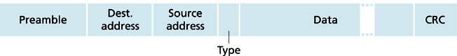
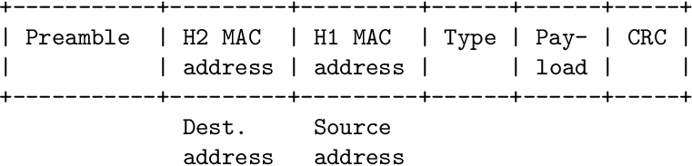
14 Estructura del frame
- Todas las tecnolog’ias Ethernet utilizan la misma estructura de
frame
(v’ease la Figura
1).
- Pre’ambulo (8 bytes): consta de XXXX XXXY donde X = 1010 1010
e Y = 1010 1011. Se utiliza para sincronizar los relojes del emisor y del
receptor que miden la duraci’on de los bits del frame.
- Dir. f’isica destino (6 bytes): dir del adaptador destino.
- Dir. f’isica fuente (6 bytes): dir del adaptador origen.
- Tipo (2 bytes): identifica el protocolo usado en la capa de red (IP, Novell
IPX, AppleTalk, etc.).
- Datos (entre 46 y 1.500 bytes): paquete de datos transportado. La capa
de red se encarga de la segmentaci’on y del relleno con ceros (si estos
fueran necesarios).
- CRC (4 bytes): CRC-32. Sirve para detectar errores de transmisi’on.
15 Tamaño m’aximo y m’inimo de frame
- Ethernet es incapaz de encapsular un paquete proveniente de la capa de
rez que ocupe m’as de 1.500 bytes. Este valor es suficientemente bajo como
para que los tiempos de espera de los adaptadores que est’an esperando a
transmitir no sea excesivo y suficientemente alto como para que el overhead
de las cabeceras sea reducido.
- Ethernet tampoco puede transportar payloads de menos de 46 bytes por
la siguiente raz’on. Si sumamos los 18 bits de cabecera que transportan
informaci’on (todos los campos excepto los bits de sicronismo) resultan 64
bytes (512 bits). La Ethernet original pod’ia extenderse hasta 200 metros
y presentaba un RTT de 50 micro-segundos, aproximadamente. En la
Ethernet original la tasa de transmisi’on era 10 Mbps y a esta tasa de bits,
512 bits tardan en inyectarse en el medio 51,2 micro-segundos. Por tanto,
cualquier estaci’on estar’ia transmitiendo a’un si ella hubiera provocado
una colisi’on. As’i, sabr’ia que tiene que volver a retransmitir el frame.
- En Ethernet de 1 Gbps o m’as el tama no m’inimo de trama aumenta
hasta 512 bytes para poder seguir creando segmentos suficientemente
largos.
- Cualquier trama con un tama no inferior al tamn no m’inimo se considera
como ruido o como el resto de una colisi’on.
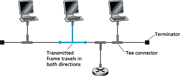
16 Ethernet 10Base2
- Creada a principios de los 90, fue una de las primeras redes de ’area local.
- Consigue 10 Mbps usando transmisi’on en banda base y permite enlaces
de hasta 200 metros de longitud (de ah’i el “2” en su nombre).
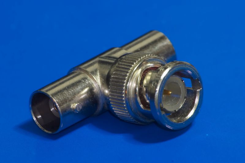
- Los adaptadores se conectan entre s’i usando cable coaxial delgado y conectores
en T (v’ease la Figura
2).
- Se trata de una tecnolog’ia donde s’olo existe un dominio de colisi’on.
Los frames se propagan en ambas direcciones, alcanzan a todos los
adaptadores, van perdiendo energ’ia en su viaje y finalmente mueren
(se aten’uan totalmente) en los terminadores (resistencias de 50 Ω).
Dicha atenuaci’on es fundamental para que la señal no rebote en los
extremos del cable y autocolisione, haciendo imposible la transmisi’on de
datos.
16.1 El cable Ethernet coaxial
- En Ethernet de medios compartidos, los enlaces se crean con cable coaxial
(v’ease la Figura ??).
- Dependiendo del tipo de cable, la m’axima separaci’on entre nodos conectados
a la red var’ia:
- Cable coaxial delgado (Thin Ethernet): 200 metros.
- Cable coaxial grueso (hick Ethernet): 500 metros.
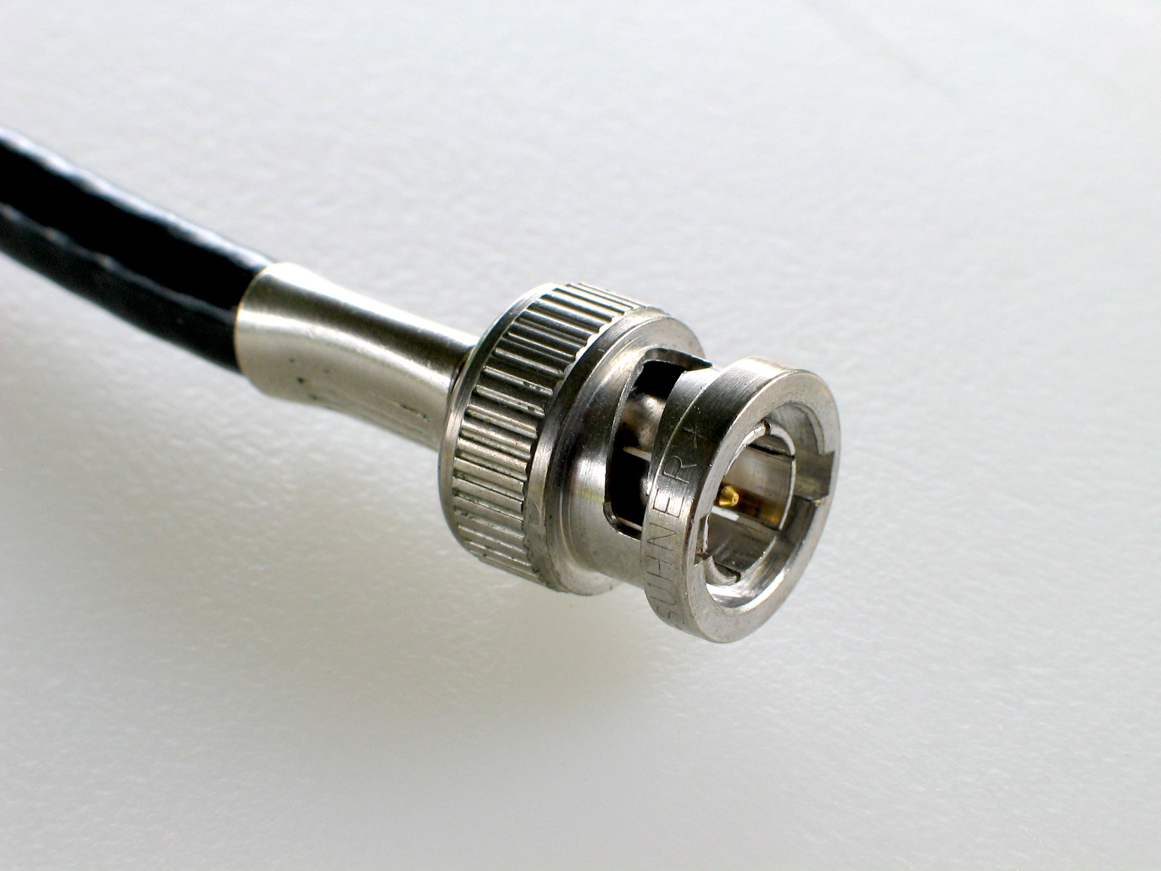
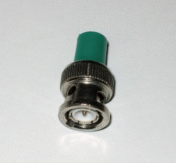
- Los nodos (hosts y otros dispositivos de conmutaci’on/repetici’on) se conectan
mediante conectores BNC (Bayonet Neill-Concelman) (v’ease la Figura
3).
16.2 El protocolo CSMA/CD en Ethernet
- El adaptador de red intenta transmitir cada frame lo antes posible, pero
primero comprueba (durante 96 tiempos de bit) a que no exista señal
“portadora” en el medio. Esto se hace para que el medio regrese a su nivel
de equilibrio tras un uso anterior
- Si durante una transmisi’on no se detecta una colisi’on, se supone que el
frame se ha transmitido con ’exito.
Sin embargo, si se detecta una colisi’on la transmisi’on se aborta inmediatamente
y se transmite una señal de jam (atasco) de 48 (32 bits seg’un CISCO) bits
iguales a 0.
- Todos los adaptadores que han producido una colisi’on ejecutan el algoritmo
de retroceso exponencial binario. Este consiste en:
- Sea n ← 1 el n’umero de colisiones experimentadas en la transmisi’on
del frame en cuesti’on.
- Mientras persista la situaci’on de colisi’on:
- Generar un n’umero entero aleatorio uniforme
K ∈{0,1, ,2m − 1}, donde m = min(n,10).
- Esperar K × 512 tiempos de bit antes de retransmitir.
- n ← n + 1.
- Si n ≥ 16 abortar transmisi’on.
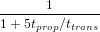
16.3 Eficiencia
16.4 Puentes
- Un puente es el nombre que recibe el dispositivo de conmutaci’on de nivel
2 usado en Ethernet xBase2 y que posee funcionalidades de routing.
- Cuando el tr’afico soportado por un tramo de red es excesivo, pueden
definirse diferentes dominios de colisi’on mediante el uso de puentes.
- Los puentes hacen las veces de conmutadores ,
permitiendo aumentar el tamaño de la red significativamente.
- La topolog’ia t’ipica es en estrella, aunque pueden darse lazos (v’ease la
Figura ??).
- Los puentes aumentan la fiabilidad de la red ya que un fallo en uno de los
extremos de un puente no tiene por qu’e afectar en los dem’as [3].
- Los puentes aumentan la seguridad ya que el tr’afico en uno de los tramos
s’olo alcanza a los dem’as cuando los datos tienen como destino hosts de
dichos tramos [3].
- Los puentes no cambian el contenido de los paquetes de datos que encaminan
hacia otros tramos de red. Los puentes no tienen direcciones f’isicas.
Ninguna trama de datos puede tener como destino ’ultimo un puente [3].
16.5 Las tablas de conmutaci’on
- Los puentes poseen una switch table con la estructura presentada en la Figura
4.
- La primera columna indica la direcci’on f’isica de los diferentes
interfaces de red conectados al puente (directamente o a
trav’es de un hub, que es el nombre que recibe un repetidor en
Ethernet)
la segunda es la boca al que se conecta cada interface y la tercera, el ’ultimo
instante en que se ha escuchado a ese interface.
16.6 Flooding (inundaci’on)
- Consiste en retransmitir un paquete de datos por todos los enlaces, excepto
por ’el que ha llegado.
- Este comportamiento es necesario para encaminar paquetes hacia hosts
que o nunca han hablado, o bien hace mucho tiempo que lo hicieron (al
menos no desde que el puente est’a funcionando).
16.7 Encaminamiento multicast
- En Ethernet se permite que un adaptador de red transmita un paquete al
resto de adaptadores de red (broadcasting).
- Cuando el paquete de datos va dirigido a la direcci’on de broadcast de
la LAN, los puentes retranmiten el paquete a todos los segmentos de red
(inundan la red).
- Para evitar bucles de retransmisi’on ,
se utilizan s’olo aquellos enlaces que pertenencen el ’arbol de expansi’on
de la red.
17 Network redundancy implies error resilience
Link and node (switch) redundancy is a way to create a fault-resistant networks. For
this reason, physical loops are common because if there is a failure in one of the
paths, there is other one to transmmit the data.
Due to a switch floods a frame when the destionation MAC address of the frame
is unknown, the same frame can return to the switch through a loop. This can result
in duplicate frames arriving at the destination device.
Moreover, when broadcast frames are used, a loop causes a broadcast strorm
because each switch floods the frame that returns to the switches through the
loop. Thus, in each iteration of the loop, switches floods an extra frame (the
frame that has been by error because the loop), consumming all the available
bandwidth.
17.1 El ’arbol de expansi’on (spanning tree)
- Es la subred formada por todos los conmutadores de la red y por un
subconjunto de enlaces de dicha red, de forma que conforman un grafo sin
lazos (un ’arbol).
- Usando el ’arbol de expansi’on es posible hacer llegar un paquete de datos
a todos los segmentos (enlaces) de la red sin provocar bucles infinitos de
retransmisi’on de paquetes de datos.
- Los conmutadores definen el ’arbol de expansi’on usando el Spanning Tree
Protocol.
17.2 The Spanning Tree Protocol (STP, IEEE 203.1D)
- STP ensures that there is only one logical path between all destinations on
the network by blocking redundant paths that could cause a loop (physical
paths still exist to provide error resilience, but they are disabled for normal
– data – traffic).
- Se utiliza para que los puentes definan sus tablas de conmutaci’on de
forma que durante el proceso de encaminamiento unicast o multicast, no
se produzcan lazos infinitos de retransmisi’on.
- Los puentes necesitan hablar entre s’i, y por tanto referenciarse. El
STP define que cada puente debe poseer un identificador ’unico de 64
bits (bridge ID). Los 16 bits m’as significativos son especificables por el
administrador del puente y por defecto valen 0x8000. El resto de bits son
especificados de forma ’unica por el fabricante. El primer paso del STP
consiste en designar un puente ra’iz (root bridge) y por definici’on ’este
ser’a el de menor bridge ID. El administrador deber’ia designar un puente
ra’iz que quedara m’as o menos en el centro topol’ogico de la red.
- Adem’as, cada puerto de un puente concreto tiene un identificador ’unico
de 16 bits (port ID). Si no se usa el STP, el byte m’as significativo
(que por defecto vale 0x80) puede ser especificado por el administrador
del puente y el menos significativo lo elige el fabricante de forma que
siempre se cumple la unicidad. Si se usa el STP, ’este definir’a los ports
ID .
De una forma un otra, el menor ID siempre deber’ia pertenecer al camino
de menor coste hacia el puente ra’iz.
- El coste de un enlace se define en funci’on de su tasa de transmisi’on. A mayor
tasa, menor coste. Un ejemplo de asignaci’on de costes aparece en la Figura
5.
- El puente ra’iz env’ia a la direcci’on f’isica multicast 01-80-C2-00-00-00
un paquete llamado BPDU (Bridge Protocol Data Unit). En este
paquete, entre otra informaci’on, se env’ia el coste acumulado
para alcanzar el puente ra’iz. En este primer env’io, el coste es
0.
- Cada puente directamente conectado al puente ra’iz recibe un BPDU e
incrementa el coste en funci’on de la tasa de bits del enlace por el que lo ha
recibido. Tras esto hace un flooding del BPDU, usando de nuevo la
direcci’on multicast. Evid’entemente, los puentes van a recibir m’ultiples
BPDU’s. Sin embargo, s’olo van a retransmitir aquellos paquetes de coste
m’inimo.
- Los enlaces por los que se han transmitido los BPDU’s de coste m’inimo conforman el ’arbol de
expansi’on.
El STP modificar’a las tablas de conmutaci’on de forma que habr’a una ruta
por defecto para aquellos paquetes de datos que no vayan dirigidos a
adaptadores de red directamente conectados a un puente, y dichas rutas
seguir’an el ’arbol de expansi’on.
- Peri’odicamente (t’ipicamente cada 5 minutos) el STP se re-ejecuta. Esto
permite adaptarse a cambios en la red. Sim embargo, en entornos con una alta
probabilidad de fallos, como pueden ser las redes instaladas en contextos
industriales, la IEEE 802.1w propuso el Rapid STP (RSTP) que tiene
un tiempo de respuesta frente a cambios topol’ogicos de 1 segundo
[1].
18 Brigde ID (BID)
The STP defines that each bridge has a 64-bit Bridge Identificator (BID). The 16
MSBs are specified by the bridge administrator and, by default, it is set to 0x8000.
The rest of bits are specified by the manufactorer of the bridge (like in the Ethernet
NICs).
The 16 MSBs is composed of 4 MSBs which represent the bridge priority and 12
LSBs with the extended system ID. This ID is the ID of the VLAN with shiwh the
BPDU is associated.
19 BPDU frames
The STP determines a root bridge for the spanning-tree instance by exchanging BPDUs.
| Field | Bytes | Meaning |
| Protocol ID | 2 | Always 0 |
| Version | 1 | Always 0 |
| Message type | 1 | Always 0 |
| Flags | 1 | Topology change and topology change ACK |
| Root ID | 8 | 2-byte priority + 6-byte MAC address of the root |
| Cost of path | 4 | Cost of the path from the bridge to the root |
| Bridge ID | 8 | 2-byte priority + 6-byte MAC address of the bridge |
| Port ID | 2 | Port number from which the BPDU was sent |
| Message age | 2 | Elapsed time from the root sent the BPDU |
| Max age | 2 | Instant of time the BPDU should be not forwarded |
| Hello time | 2 | Interval used by root to send BPDUs |
| Forward delay | 2 | Time that that bridge waits before anunce a change in the topology |
20 Algorithm for the selection of the root bridge
- When a bridge is power on, it thinks that it is the root bridge.
- Each bridge maintais local information about its own BID, root BID and
the cost of the path to the root.
- BPDU frames are not forwarded. BPDU frames are computed and flooded,
by default, every 2 seconds.
- To determine the cost and root BID in a BPDU frame, the bridge checks if
the root BID received in a BPDU is lower than its localoot BID, it updates
the local root BID, it adds the cost of the receiving ling to the cost to the
root BID and includes this information in the future BPDF messages.
- After a number of iteration that depends on the size of the network, all
the briddes determines the root BID and the cost to reach it.
21 Port cost
Costes recomentados por la norma IEEE 802.1 para el STP.
| Tasa de bits | Coste |
|
|
| 4 Mbps | 250 |
| 10 Mbps | 100 |
| 16 Mbps | 62 |
| 100 Mbps | 19 |
| 1 Gbps | 4 |
| 10 Gbps | 2 |
| |
22 The Spanning Tree Algorithm (STA)
Determines which ports of the bridges on a broadcast domain need to be configured
for blocking to prevent loops from ocurring.
- Determine the root bridge: The root bridge is the one with the lowest
BID. Each bridge sends out BPDU frames containing the BID and the root
ID
every 2 seconds. When a bridge receives a BPDU, computes the minimun
of the actual root IP it has and the received in the BPDU, updates its
root ID and replaces the root IP by the minimun on the flooded BPDU.
- Each bridge determines the best path to the root bridge: The
path information if determined by summing up the indivial port costs
along the path from the destination to the root bridge. The port with the
lowest cost path to the root is selected to belongs to the spanning-tree. If
a bridge has two paths with the same cost, the bridge with lower BID is
selected to be in the spanning tree. In any case, when a port is designed
for beeing in the spanning tree, there is a forward delay (15 seconds by
default) in which the bridge waits to use that port. This prevents from
oscillations in the learned topology.
23 Port clasification
- Root ports: Only exists on non-root bridges and only one per bridge. It
is the port with the lowest path cost to the root bridge.
- Designated ports: For the root bridge, all ports are designated ports.
For non-root bridges, only exist one per bridge and is the port. A port is a
designated port if in the other extreme of the link, the bridge has classified
his port as root.
- Non-designated ports: The rest of ports.
24 Largest network diameter
A seven-bridge diameter is the largest diameter that STP permits because of
convergence times (time that it takes to recalculate the spanning tree if a bridge or a
link fails). This time is, in average, of 14 seconds. A link is considered broken
if has not transmited 10 consecutive BPDUs (no BPDU nothing received
in 20 seconds). When this happens, the bridge send a message to the root
bridge which broadcast the change to the rest of bridges which re-run the
SPA.
25 The Rapid STP (RTSP, IEEE 802.1w)
A newer and much faster version of the STP (from up to 50 seconds to uo to 6
seconds). The key is to define alternate or backup ports that can be inmediately used
in case of network change.
It is backward compatible witn 802.1D.
26 Multiple STP (MSTP
Allow to use VLANs in the same spanning-tree instance.
27 Ethernet conmutada
- Probablemente influenciados por la tecnolog’ia de transmisi’on de datos
ATM, los diseñadores de la red Ethernet decidieron cambiar los enlaces
compartidos por enlaces punto a punto full-duplex. El motivo: no existen
colisiones ya que s’olo hay dos adaptadores de red conectados a cada
enlace, uno el del conmutador
o del hub
y otro el del host (u otro conmutador/hub). Hay otra forma de indicar esto
mismo y es que podemos entender que un conmutador crea un dominio
de colisi’on diferente para cada boca y si s’olo conectamos un host (o un
switch) a cada boca, es imposible procovocar colisiones.
- La topolg’ia t’ipica de una red Ethernet conmutada es la de estrella,
aunque tambi’en pueden crearse redes con ciclos.
27.1 Concentradores (hubs)
- Los concentradores (o hubs) son b’asicamente repetidores (dispositivos de
regeneraci’on de señales digitales que funcionan a nivel de la capa f’isica)
copiando a sus salidas los bits que llegan a una de sus entradas (v’ease la
Figura
6).
- Como repetidores digitales, sirven para regenerar las señales durante largos
tr’ansitos o situaciones extremas de ruido [2].
- No entienden los protocolos de la capa de enlace de datos (ni por supuesto los
superiores).
- No crean dominios de colisi’on, s’olo los extienden. En este sentido todos
los nodos que se conectan mediante un hub acceden al medio usando
CSMA/CD.
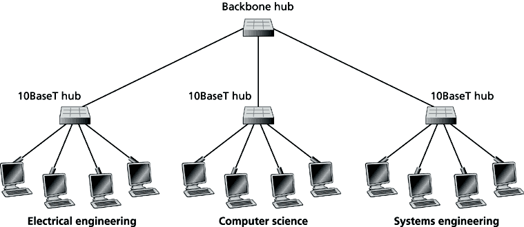
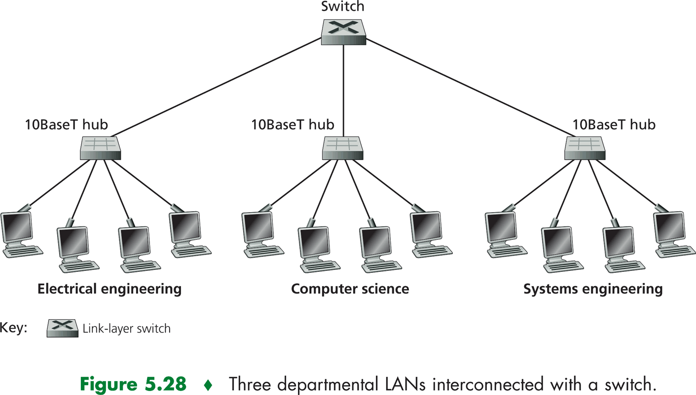
27.2 Conmutadores (switches)
- Los conmutadores Ethernet son dispositivos de conmutaci’on de paquetes
de datos que funcionan a nivel de la capa de enlace de datos.
- A diferencia de los hubs, pueden interconectar diferentes tecnolog’ias
Ethernet.
- Tambi’en a diferencia de los hubs, separan los dominios de colisi’on. Por
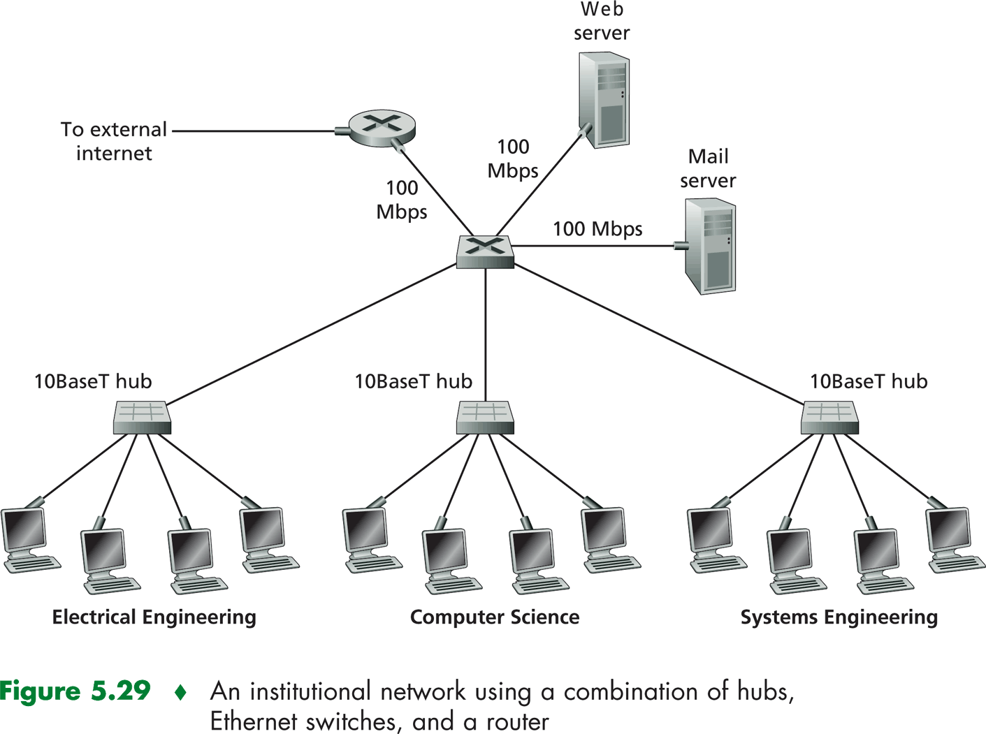
ejemplo, en la red mostrada en la Figura
7 existen 3 dominios de colisi’on diferentes, uno para cada departamento. En la
Figura
8 se presenta otro ejemplo algo m’as complejo.
- Como se desprende de los anteriores ejemplos, los switches deben ejecutar el
protocolo CSMA/CD s’olo cuando el enlace involucrado no sea full-duplex (que
normalmente lo es).
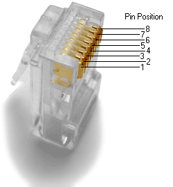
27.3 El cable usado en Ethernet conmutada
- Utiliza el conector RJ-45 (Registered Jack), que posee 8 contactos (v’ease la
Figura
9).
- Existen dos tipos de cables:
- El cable directo (straight-thru), que se reconoce por tener id’enticos
terminales. Se utiliza para conectar dispositivos diferentes (PC-switch, por
ejemplo). V’ease la Figura
10.
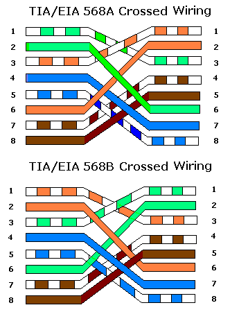
- El cable cruzado (crossover) que se reconoce por tener terminales
diferentes. Se utiliza para conectar dispositivos iguales (PC-PC, por
ejemplo). V’ease la Figura
11.
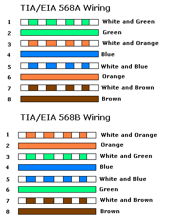
- Existen 2 normas (A y B), que cambian en los colores que se le asignan a los
cables. Por supuesto, esto no afecta a la funcionalidad del cable.
- Finalmente, los cables pueden estar blindados (STP - Shielded Twisted
Pair), o no (UTP Un-shielded Twisted Pair), y tener m’as o menos
trenzas. El STP es mejor que el UTP y cuantas m’as trenzas existan,
tambi’en mejor (v’ease la Secci’on ??). Adem’as, el n’umero de trenzas
del par que se utiliza para enviar no debe ser m’ultiplo del n’umero
de trenzas del par que se utiliza para recibir, para evitar la diafon’ia
(cross-talk).
27.4 Encaminamiento usando conmutadores
- Id’entico al encaminamiento usando puentes.
27.5 Ethernet 10BaseT y Ethernet 100BaseT
- Son las m’as usadas actualmente.
- 10BaseT utiliza codificaci’on Manchester.
- Funcionan (respectivamente) a 10 Mbps y a 100 Mbps, transmiten en
banda base y utilizan (t’ipicamente) par trenzado (T).
- Usando par trenzado de cobre no suele ser posible separar m’as de 100
metros el concentrador de ninguno de los nodos. Para mayores distancias
se puede utilizar fibra ’optica que es mucho menos sensible al ruido.
27.6 El cable Ethernet 10BaseT y Ethernet 100BaseT
- En 10BaseT y 100BaseT s’olo se usan (de los 8 posibles) 4 hilos, dos para
enviar y otros dos para recibir. Los hilos 4, 5, 7 y 8 no se utilizan.
- El cable directo conecta los contactos 1 (Tx_D1+ ),
2 (Tx_D1- ),
3 (Rx_D2+ )
y 6 (Rx_D2- )
de un conector con los respectivos contactos del otro conector. V’ease la
Figura 10.
- El cable cruzado conecta los contactos 1 (Tx_D1+), 2 (Tx_D1-), 3
(Rx_D2+) y 6 (Rx_D2-) de un conector con los contactos 3 (Rx_D2+), 6
(Rx_D2-), 1 (Tx_D1+) y 2 (Tx_D1-) del otro conector, respectivamente.
V’ease la Figura 11.
27.7 Ethernet 100Base{T—F}X
- Igual que 100BaseT, pero:
- Utiliza la codificaci’on 4B/5B.
- Requiere cableado UTP Cat5 o superior (TX) o fibra ’optica (FX).
27.8 Ethernet Gigabit Ethernet (1000BaseT) y Ethernet 10 Gigabit
- Son mejoras de (y compatibles con) las normas 10BaseT y 100BaseT que
permiten alcanzar 1 Gbps y 10 Gbps, respectivamente.
- Para cobre, utiliza codificaci’on 4D-PAM5 .
- La transmisi’on y recepci’on de datos se realiza a la vez en cada par
(usando una selecci’on adecuada de voltajes para los s’imbolos 4D-PAM5
se puede deshacer la colisi’on de dos s’imbolos).
- En fibra, se usa la codificaci’on 8B/10B.
27.9 El cable Ethernet Gigabit (1000BaseT) y Ethernet 10 Gigabit
- Utiliza 8 hilos (4 pares). Es compatible con las normas “inferiores”.
- El cable directo conecta los contactos 1 (TX_D1+), 2 (TX_D1-), 3
(RX_D2+), 4 (Bi_D3+), 5 (Bi_D3-), 6 (RX_D2-), 7 (Bi_D4+) y 8
(Bi_D4-) de un conector con los respectivos contactos del otro conector.
Bi_D = Bidirectional Data. V’ease la Figura 10.
- El cable cruzado conecta los contactos 1 (TX_D1+), 2 (TX_D1-), 3
(RX_D2+), 4 (Bi_D3+), 5 (Bi_D3-), 6 (RX_D2-), 7 (Bi_D4+) y 8
(Bi_D4-) de un conector con los contactos 3 (RX_D2+), 6 (RX_D2-),
1 (TX_D1+), 7 (Bi_D4+), 8 (Bi_D4-), 2 (TX_D1-), 4 (Bi_D3+) y 5
(Bi_D3-) del otro conector, respectivamente. V’ease la Figura 11.
27.10 El cable 1000BaseSX y 1000BaseLX
- Utilizan dos fibras ’opticas, una para enviar y otra para recibir.
28 Resumen
Ojo, hay verbatim oculto!
29 Encaminamiento entre BSSs
30 Mobilidad entre BSSs
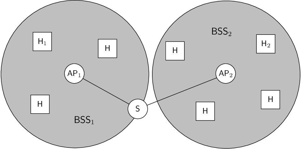
- Supongamos que en el ejemplo de la Figura 12, H1 se mueve desde la BSS1
a la BSS2.
- Cuando se usa un hub para conectar las BSS no existen problemas para
entregar los frames al nodo m’ovil ya que todos los frames se retransmiten
a todas las BSSs. Sin embargo, cuando hay un conmutador ’este debe
actualizar su switch table lo m’as frecuentemente posible (idealmente, en
cuanto H1 se asocia a AP2).
References
[1] The abcs of spanning tree protocol. Contemporary Controls, 2006.
[2] James F. Kurose and Keith W. Ross. Computer Networking: A
Top-Down Approach Featuring the Internet (2nd Edition). Addison Wesley,
2003.
[3] William Stallings. Comunicaciones y Redes de Computadores (7a
Edici’on). Prentice Hall, 2004.